This page lists down detailed and information rich UFT (formerly QTP) Tutorials for beginners as well as experienced users of UFT. If you are a beginner, it is advised that you go through the articles one after the other as mentioned in the list. So let's get started UFT/QTP Tutorials for Beginners. What is QTP Tutorial? HP QuickTest Professional (QTP) is an automated functional testing tool that designed to apply automated regression testing to find out the gaps, errors/defects in contrary to the actual/desired results of the application under test. Qtp tutorial for beginners. This tutorial is designed for Software Testing Professionals with a need to understand the QTP in detail along with its simple overview, and practical examples. This tutorial will give you enough ingredients to start with QTP from where you can take yourself at higher level of expertise.
ASME B31.3 Acceptance criteria for welds

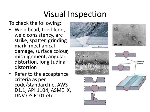
Weld visual inspection shall be performed by personnel trained through an established program that reflects the intent of the recommended guidelines provided in ASNT-TC-1A, EN473, AWS B1.11, CAN/CGSB-48.972-2000, or EN 970. Ideneb 1.3. Personnel conducting weld visual inspection for final product acceptance shall. The Visual Weld Inspection Checklist is recommended as a best practice for supplier's approved weld inspectors. 4.5 The inspectors' tool kit shall include, as a minimum, the following tools: VISUAL WELD INSPECTORS TOOL KIT TOOL TOOL REQUIREMENT RECOMMENDED Flashlight Xenon or Krypton bulb 2AA or 2AAA size batteries Fillet Weld Gages Standard. Visual Inspection Responsibilities. When – Final visual inspections must be performed: a) When the weld is complete, and in the final sur-face and heat treated conditions b) Before other NDT (when required) c) Before being made inaccessible for inspection 2. Where – the weld inspection zone: a) All work - Completed weld faces plus ½ inch on.
ASME B31.3 Acceptance criteria for welds
As per ASME B31.3 Table 341.3.2 Acceptance criteria for welds, is it important to meet all the acceptable values mentioned in the criteria. For eg. lack of root penetration for Normal and Category M fluid - Girth, Miter groove and branch connection shows B as acceptance criteria. Notation B has two acceptable values in the table. One for depth i.e. <1mm and <0.2Tw (both are less than or equal to) and the other for cumulative length i.e. <38mm (also less than or equal to) in any 150mm weld length. Does this mean that both depth and length should be within the limits to accept the weld. RT cannot detect the depth as it is 2D image, so if in this case when the depth cannot be determined, is it possible to reject the weld? Is there an interpretation of this available from ASME?
Appreciate your help.

Visual Weld Inspection Criteria

Weld visual inspection shall be performed by personnel trained through an established program that reflects the intent of the recommended guidelines provided in ASNT-TC-1A, EN473, AWS B1.11, CAN/CGSB-48.972-2000, or EN 970. Ideneb 1.3. Personnel conducting weld visual inspection for final product acceptance shall. The Visual Weld Inspection Checklist is recommended as a best practice for supplier's approved weld inspectors. 4.5 The inspectors' tool kit shall include, as a minimum, the following tools: VISUAL WELD INSPECTORS TOOL KIT TOOL TOOL REQUIREMENT RECOMMENDED Flashlight Xenon or Krypton bulb 2AA or 2AAA size batteries Fillet Weld Gages Standard. Visual Inspection Responsibilities. When – Final visual inspections must be performed: a) When the weld is complete, and in the final sur-face and heat treated conditions b) Before other NDT (when required) c) Before being made inaccessible for inspection 2. Where – the weld inspection zone: a) All work - Completed weld faces plus ½ inch on.
ASME B31.3 Acceptance criteria for welds
As per ASME B31.3 Table 341.3.2 Acceptance criteria for welds, is it important to meet all the acceptable values mentioned in the criteria. For eg. lack of root penetration for Normal and Category M fluid - Girth, Miter groove and branch connection shows B as acceptance criteria. Notation B has two acceptable values in the table. One for depth i.e. <1mm and <0.2Tw (both are less than or equal to) and the other for cumulative length i.e. <38mm (also less than or equal to) in any 150mm weld length. Does this mean that both depth and length should be within the limits to accept the weld. RT cannot detect the depth as it is 2D image, so if in this case when the depth cannot be determined, is it possible to reject the weld? Is there an interpretation of this available from ASME?
Appreciate your help.
Visual Weld Inspection Criteria
Visual Weld Inspection Acceptance Criteria Example
Aws Visual Inspection Criteria
Visual Weld Inspection Acceptance Criteria Template
Visual Weld Inspection Acceptance Criteria Requirements
by online welding courses – non destructive testing
